
RADIOGRAPHY (RT)
- 1. RAMCO INSTITUTE OF TECHNOLOGY Mr.M.LAKSHMANAN Assistant Professor (Senior Grade) Department of Mechanical Engineering
- 3. Syllabus Principle, interaction of X-Ray with matter, imaging, film and film less techniques, types and use of filters and screens, geometric factors, Inverse square law, characteristics of films - graininess, density, speed, contrast, characteristic curves, Penetrameters, Exposure charts, Radiographic equivalence. Fluoroscopy- xero- Radiography, Computed Radiography, Computed Tomography
- 4. Introduction Radiography uses penetrating radiation that is directed towards a component. The component stops some of the radiation. The amount that is stopped or absorbed is affected by material density and thickness differences. These differences in “absorption” can be recorded on film, or electronically. Detection of internal defects such as porosity, voids and inclusions With proper orientation, planar defects can also be detected.
- 5. Also suitable for detecting changes in • Material composition • Thickness measurement • Locating defective parts or components from • Assembled part
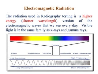
- 6. Electromagnetic Radiation The radiation used in Radiography testing is a higher energy (shorter wavelength) version of the electromagnetic waves that we see every day. Visible light is in the same family as x-rays and gamma rays.
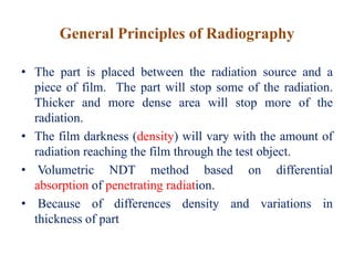
- 7. General Principles of Radiography • The part is placed between the radiation source and a piece of film. The part will stop some of the radiation. Thicker and more dense area will stop more of the radiation. • The film darkness (density) will vary with the amount of radiation reaching the film through the test object. • Volumetric NDT method based on differential absorption of penetrating radiation. • Because of differences density and variations in thickness of part
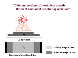
- 8. “Different portions of a test piece absorb Different amount of penetrating radiation” Top view of developed film X-ray film = more exposure = less exposure
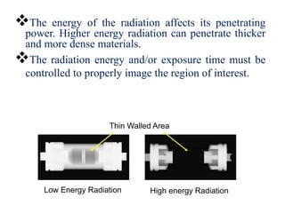
- 9. The energy of the radiation affects its penetrating power. Higher energy radiation can penetrate thicker and more dense materials. The radiation energy and/or exposure time must be controlled to properly image the region of interest. Thin Walled Area Low Energy Radiation High energy Radiation
- 10. Radiography Radiography is a method of non-destructive testing where many types of manufactured components can be examined to verify the internal structure and integrity of the specimen. Industrial Radiography can be performed utilizing either X- rays or gamma rays. Both are forms of electromagnetic radiation. The difference between various forms of electromagnetic energy is related to the wavelength. X and gamma rays have the shortest wavelength and this property leads to the ability to penetrate, travel through, and exit the various materials.
- 11. Radiographic testing • Radiographic testing is a non-destructive testing of components and assemblies that is based on differential absorption of penetrating radiation- either electromagnetic radiation of very short wave-lengths or particulate radiation by the part or test piece being tested. • Because of differences in density and variations in thickness of the part, or differences in absorption characteristics caused by variation in composition, different portions of a test piece absorb different amounts of penetrating radiation. • Unabsorbed radiation passing through the part can be recorded on film or photosensitive paper, viewed on a florescent screen or monitored by various types of electronic radiation detectors.
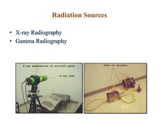
- 12. Radiation Sources • X-ray Radiography • Gamma Radiography
- 13. Gamma Radiography •Gamma rays are produced by a radioisotope. •A radioisotope has an unstable nuclei that does not have enough binding energy to hold the nucleus together. •The spontaneous breakdown of an atomic nucleus resulting in the release of energy and matter is known as radioactive decay.
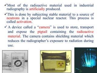
- 14. Most of the radioactive material used in industrial radiography is artificially produced. This is done by subjecting stable material to a source of neutrons in a special nuclear reactor. This process is called activation. A device called a “camera” is used to store, transport and expose the pigtail containing the radioactive material. The camera contains shielding material which reduces the radiographer’s exposure to radiation during use.
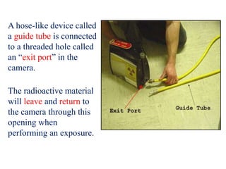
- 15. A hose-like device called a guide tube is connected to a threaded hole called an “exit port” in the camera. The radioactive material will leave and return to the camera through this opening when performing an exposure.
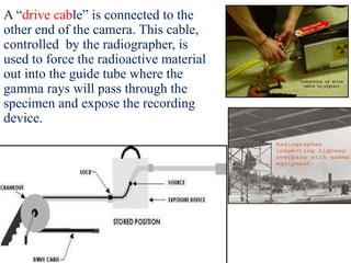
- 16. A “drive cable” is connected to the other end of the camera. This cable, controlled by the radiographer, is used to force the radioactive material out into the guide tube where the gamma rays will pass through the specimen and expose the recording device.
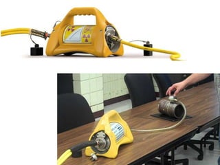
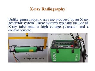
- 19. X-ray Radiography Unlike gamma rays, x-rays are produced by an X-ray generator system. These systems typically include an X-ray tube head, a high voltage generator, and a control console.
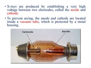
- 20. • X-rays are produced by establishing a very high voltage between two electrodes, called the anode and cathode. • To prevent arcing, the anode and cathode are located inside a vacuum tube, which is protected by a metal housing.
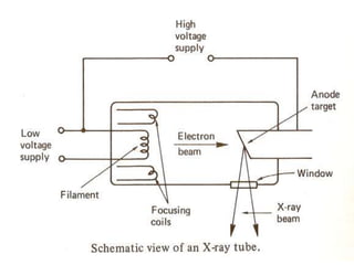
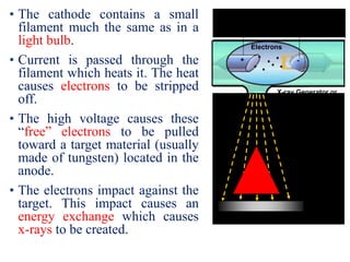
- 22. • The cathode contains a small filament much the same as in a light bulb. • Current is passed through the filament which heats it. The heat causes electrons to be stripped off. • The high voltage causes these “free” electrons to be pulled toward a target material (usually made of tungsten) located in the anode. • The electrons impact against the target. This impact causes an energy exchange which causes x-rays to be created. High Electrical Potential Electrons -+ X-ray Generator or Radioactive Source Creates Radiation Exposure Recording Device Radiation Penetrate the Sample
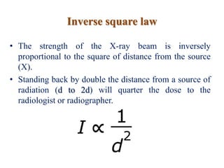
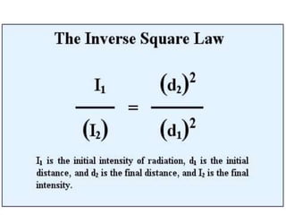
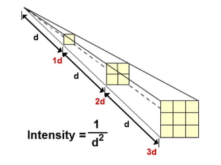
- 23. Inverse square law • The strength of the X-ray beam is inversely proportional to the square of distance from the source (X). • Standing back by double the distance from a source of radiation (d to 2d) will quarter the dose to the radiologist or radiographer.
- 26. Penetrameters • A "Penetrameters" is a device used in radiographic testing to evaluate the quality of radiographic images. penetrameters are referred to as image quality indicators (IQI). • Penetrameters come in a wide range of shapes, sizes, and configurations. They can be small metal plates containing the same- or variable-sized holes, or they can be a series of variable-diameter wires contained in plastic packets.
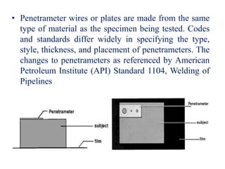
- 27. • Penetrameter wires or plates are made from the same type of material as the specimen being tested. Codes and standards differ widely in specifying the type, style, thickness, and placement of penetrameters. The changes to penetrameters as referenced by American Petroleum Institute (API) Standard 1104, Welding of Pipelines
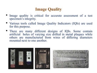
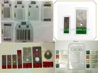
- 28. Image Quality • Image quality is critical for accurate assessment of a test specimen’s integrity. • Various tools called Image Quality Indicators (IQIs) are used for this purpose. • There are many different designs of IQIs. Some contain artificial holes of varying size drilled in metal plaques while others are manufactured from wires of differing diameters mounted next to one another.
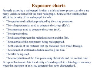
- 30. Exposure charts Properly exposing a radiograph is often a trial and error process, as there are many variables that affect the final radiograph. Some of the variables that affect the density of the radiograph include: • The spectrum of radiation produced by the x-ray generator. • The voltage potential used to generate the x-rays (KeV). • The amperage used to generate the x-rays (mA). • The exposure time. • The distance between the radiation source and the film. • The material of the component being radiographed. • The thickness of the material that the radiation must travel through. • The amount of scattered radiation reaching the film. • The film being used. • The concentration of the film processing chemicals and the contact time. It is possible to calculate the density of a radiograph to a fair degree accuracy when the spectrum of an x-ray generator has been characterized.
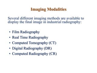
- 33. Imaging Modalities Several different imaging methods are available to display the final image in industrial radiography: • Film Radiography • Real Time Radiography • Computed Tomography (CT) • Digital Radiography (DR) • Computed Radiography (CR)
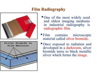
- 34. Film Radiography •One of the most widely used and oldest imaging mediums in industrial radiography is radiographic film. •Film contains microscopic material called silver bromide. •Once exposed to radiation and developed in a darkroom, silver bromide turns to black metallic silver which forms the image.
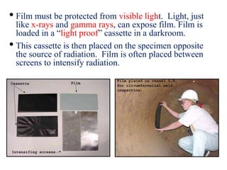
- 35. • Film must be protected from visible light. Light, just like x-rays and gamma rays, can expose film. Film is loaded in a “light proof” cassette in a darkroom. • This cassette is then placed on the specimen opposite the source of radiation. Film is often placed between screens to intensify radiation.
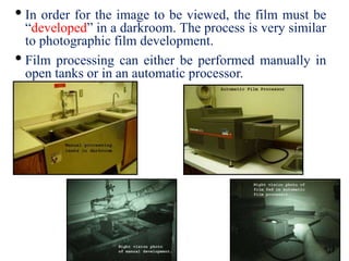
- 36. • In order for the image to be viewed, the film must be “developed” in a darkroom. The process is very similar to photographic film development. • Film processing can either be performed manually in open tanks or in an automatic processor.
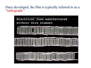
- 37. Once developed, the film is typically referred to as a “radiograph.”
- 38. Digital Radiography • One of the newest forms of radiographic imaging is “Digital Radiography”. • Requiring no film, digital radiographic images are captured using either special phosphor screens or flat panels containing micro-electronic sensors. • No darkrooms are needed to process film, and captured images can be digitally enhanced for increased detail. • Images are also easily archived (stored) when in digital form.
- 39. There are a number of forms of digital radiographic imaging including: Computed Radiography (CR) Real-time Radiography (RTR) Direct Radiographic Imaging (DR) Computed Tomography
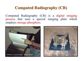
- 40. Computed Radiography (CR) Computed Radiography (CR) is a digital imaging process that uses a special imaging plate which employs storage phosphors.
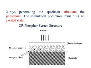
- 41. CR Phosphor Screen Structure X-rays penetrating the specimen stimulate the phosphors. The stimulated phosphors remain in an excited state. X-Rays Phosphor Layer Protective Layer SubstratePhosphor Grains
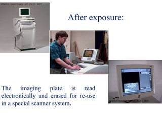
- 42. After exposure: The imaging plate is read electronically and erased for re-use in a special scanner system.
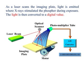
- 43. As a laser scans the imaging plate, light is emitted where X-rays stimulated the phosphor during exposure. The light is then converted to a digital value.
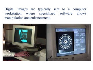
- 44. Digital images are typically sent to a computer workstation where specialized software allows manipulation and enhancement.
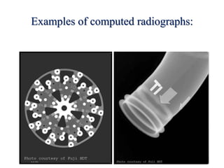
- 45. Examples of computed radiographs:
- 46. Real-Time Radiography (RTR) • Real-time radiography (RTR), or real-time radioscopy, is a non destructive test (NDT) method whereby an image is produced electronically, rather than on film, so that very little lag time occurs between the item being exposed to radiation and the resulting image. • In most instances, the electronic image that is viewed results from the radiation passing through the object being inspected and interacting with a screen of material that fluoresces or gives off light when the interaction occurs. • The fluorescent elements of the screen form the image much as the grains of silver form the image in film radiography.
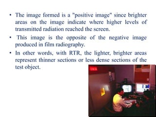
- 47. • The image formed is a "positive image" since brighter areas on the image indicate where higher levels of transmitted radiation reached the screen. • This image is the opposite of the negative image produced in film radiography. • In other words, with RTR, the lighter, brighter areas represent thinner sections or less dense sections of the test object.
- 48. • Because image acquisition is almost instantaneous, X-ray images can be viewed as the part is moved and rotated. • Manipulating the part can be advantageous for several reasons: It may be possible to image the entire component with one exposure. Viewing the internal structure of the part from different angular prospective can provide additional data for analysis. Time of inspection can often be reduced.
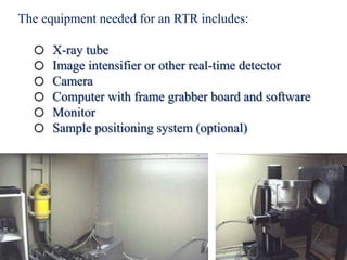
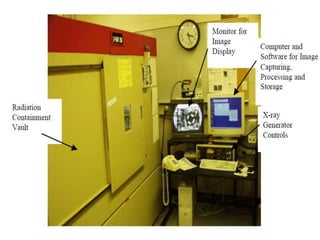
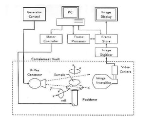
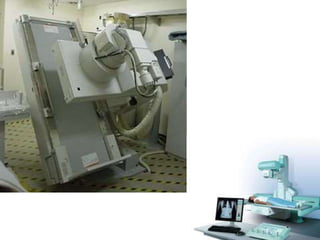
- 49. The equipment needed for an RTR includes: o X-ray tube o Image intensifier or other real-time detector o Camera o Computer with frame grabber board and software o Monitor o Sample positioning system (optional)
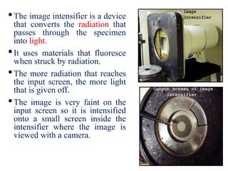
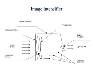
- 52. •The image intensifier is a device that converts the radiation that passes through the specimen into light. •It uses materials that fluoresce when struck by radiation. •The more radiation that reaches the input screen, the more light that is given off. •The image is very faint on the input screen so it is intensified onto a small screen inside the intensifier where the image is viewed with a camera.
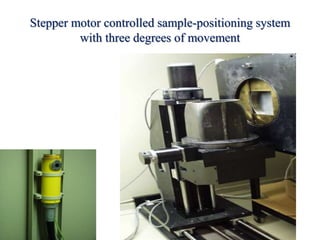
- 54. Stepper motor controlled sample-positioning system with three degrees of movement
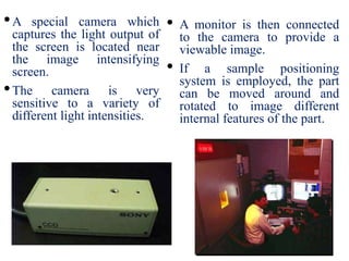
- 55. •A special camera which captures the light output of the screen is located near the image intensifying screen. •The camera is very sensitive to a variety of different light intensities. • A monitor is then connected to the camera to provide a viewable image. • If a sample positioning system is employed, the part can be moved around and rotated to image different internal features of the part.
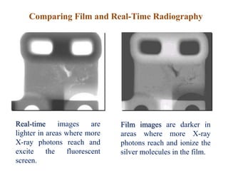
- 56. Comparing Film and Real-Time Radiography Real-time images are lighter in areas where more X-ray photons reach and excite the fluorescent screen. Film images are darker in areas where more X-ray photons reach and ionize the silver molecules in the film.
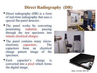
- 57. Direct Radiography (DR) • Direct radiography (DR) is a form of real-time radiography that uses a special flat panel detector. • The panel works by converting penetrating radiation passing through the test specimen into minute electrical charges. • The panel contains many micro- electronic capacitors. The capacitors form an electrical charge pattern image of the specimen. • Each capacitor’s charge is converted into a pixel which forms the digital image.
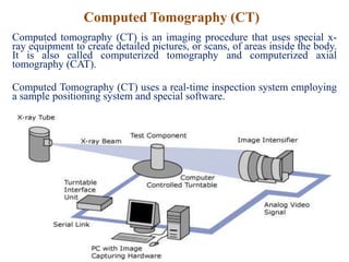
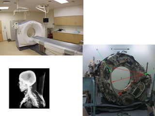
- 58. Computed Tomography (CT) Computed tomography (CT) is an imaging procedure that uses special x- ray equipment to create detailed pictures, or scans, of areas inside the body. It is also called computerized tomography and computerized axial tomography (CAT). Computed Tomography (CT) uses a real-time inspection system employing a sample positioning system and special software.
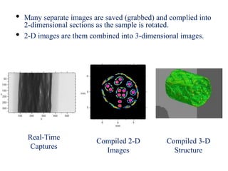
- 59. • Many separate images are saved (grabbed) and complied into 2-dimensional sections as the sample is rotated. • 2-D images are them combined into 3-dimensional images. Real-Time Captures Compiled 2-D Images Compiled 3-D Structure
- 61. Fluoroscopy Fluoroscopy is a study of moving body structures-similar to an X-ray "movie." A continuous X-ray beam is passed through the body part being examined. The beam is transmitted to a TV-like monitor so that the body part and its motion can be seen in detail. Fluoroscopy, as an imaging tool, enables physicians to look at many body systems.